ARDUINO LAMPION
So why not build a lamp directly with Arduin and RGB LED strip? We can control it all over Bluetooth from your mobile. This will be Arduino blonde. What do you think?
We will be able to choose the lampion color, stroboscope effect and colorful music! Who will really try, add other modes according to themselves. We will create an Android app in the online graphics IDE . With the Arduin, Bluetooth, and NeoPixel LED strips, we can color everything in color and manage it remotely from the mobile phone. It will also fit on the Christmas tree. Interesting is the flexibility of such a simple Arduino project, battery power and compact dimensions. NeoPixel LEDs are really good and they can enjoy a lot of fun.
Arduino lampion – let’s go!
First, choose the appropriate components for the construction. As a base, we need some small Arduino. We use Arduino NANO because it is compact and can be directly connected to the computer. We also need a Bluetooth module HC-05 for wireless communication with mobile and RGB LED tapes. A 3.7V LiPol battery with a charging module and a 5V inverter boosting power supply will also be useful to keep the lamp independent of power from the power supply. We use a cheap IKEA shade as the lantern body.
When designing hardware, everything went smoothly. I stopped when I wrote the code. I refreshed the “delay” without delay () using the Arduino time of millis (). Because delay () and serial communication can not be used unless the delay is really small. I tried my favorite method of “attempting error”. After a while of work, everything succeeded. Now let’s look at the process in more detail.
Crash ai2.appinventor.mit.edu graphical IDE
First create an account, it’s great to use pairing with a Google Account. This online IDE for creating Android apps is great for both beginners and advanced. App creation is intuitive. Also, there are plenty of examples in IDE that can be easily done in your own project. Personally, the simplest initialization of Bluetooth and subsequent communication with Arduin is most suitable for me. For almost every project I use this online IDE as a universal driver and display for Arduino. It basically replaces buttons, potentiometers, displays, keyboards. Whatever he likes. And when someone sees how you control things on the phone, he says, “How did you do it?” You only answer: “You are not still in APP Inventor yet?”
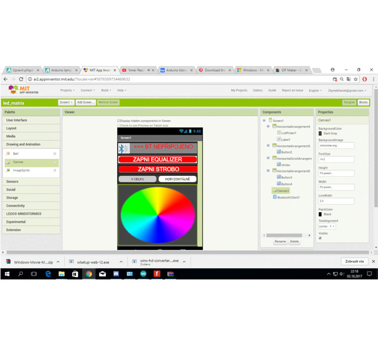
After clicking the link and successfully signing in to the online IDE we see the design screen. Here, the application controls are created. At the top right is the ‘Blocks’ button, which switches to graphical code stacking, just like with Mblock you know from mBot robots.
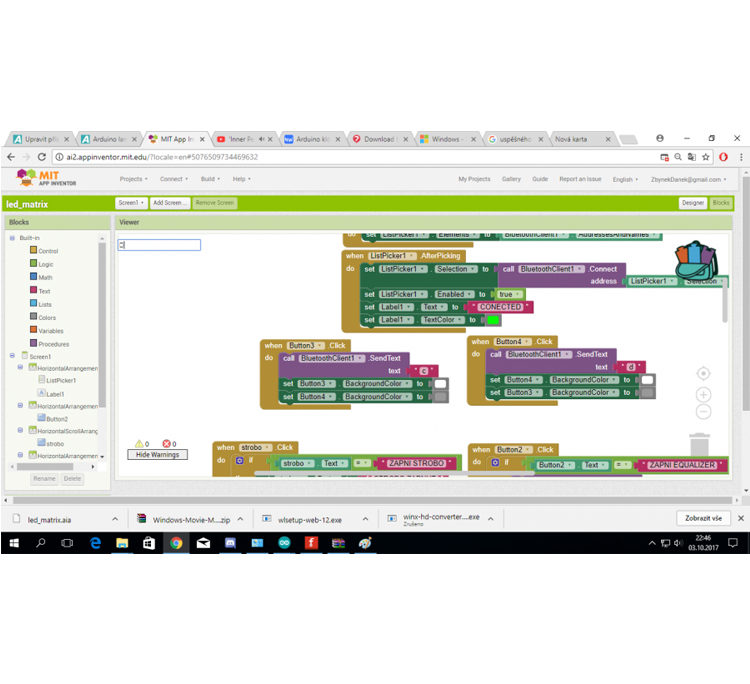
Graphical part of composing blocks of code
I attach the application file as well as the application code that you open in the online IDE. Click on ‘project ==> import project from my computer’ to insert the downloaded ‘.aia file name’ from the link.
More specifically, we will focus on the Android IDE online next time. Here is a link to a lot of useful tutorials .
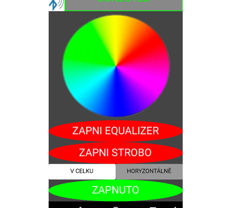
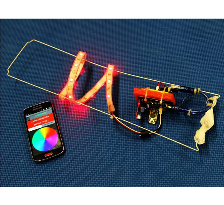
The resulting application looks like this in the mobile display.
First activate communication with the Bluetooth module HC-05. In the application, you can choose whether the setting should apply to the entire band (in the whole) and / or sequentially for each LED (horizontally). You can set the color in the color wheel and activate the Equalizer and Strobe functions. The equalizer converts the signal from the microphone to its intensity to the color effects of the LED. The stroboscope then creates a light effect, as we know it from various dance events. It is best to try it out.
Construction of Arduino lampion
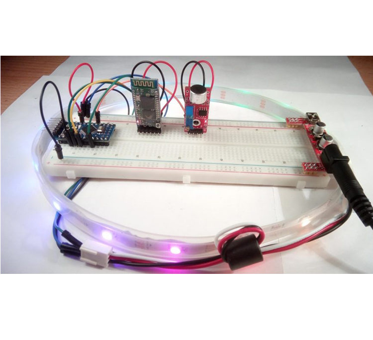
Ideal is to connect Arduino and individual modules to the contact field to test everything comfortably.
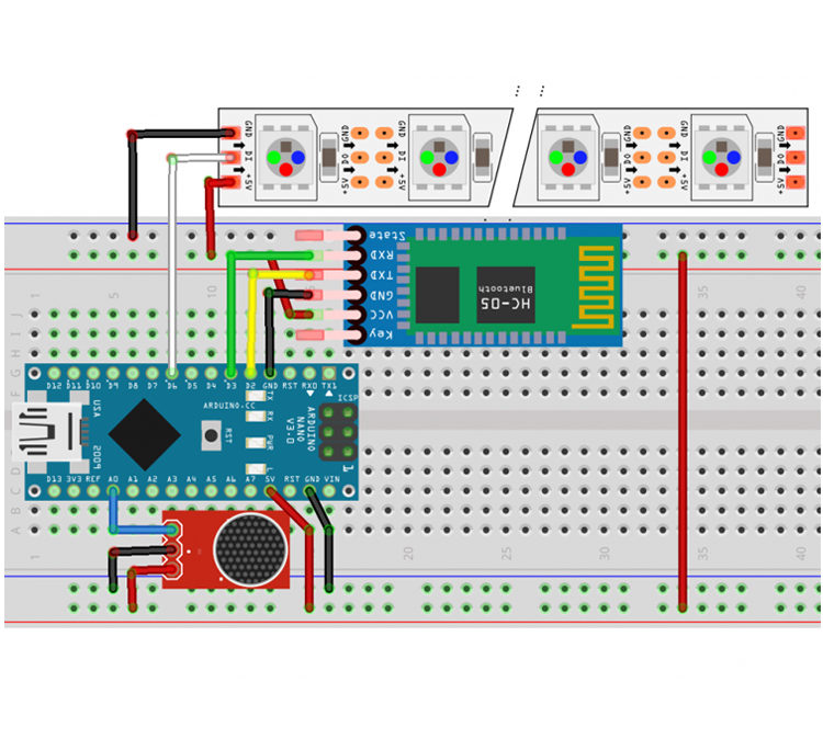
Scheme of experimental connection of Arduino lampion
The contact box shows Arduino NANO with Bluetooth and audio module attached. The LED strip is also connected. It does not include LiPol batteries, a charging module, and an upgrading power supply.
The following figure shows experimental wiring to test functionality.
Before importing the code, import the NeoPixel IDE library into Arduino . Copy the following code to the Arduino IDE. Linking individual modules and pins is at the beginning of the Arduino code.
/ * Pin
* HC-05
* Tx 2
* R 3
* VCC 5V +
* GND GND
*
* microphone sensor
* Vcc 5V +
* GND GND
* A0 – A0
*
* NeoPixel strap
* DIN 6
* VCC 5V +
* GND GND
* /
int block ; // the registry value const int sampleWindow = 50 ; // microphone data delay unsigned int sample ; #include < Adafruit_NeoPixel . h > // library neo_pixel tape #ifdef __AVR__
#include < avr / power . h >
#endif
#define PIN 6 // from LED LED Adafruit_NeoPixel strip = Adafruit_NeoPixel ( 60 , PIN , NEO_GRB + NEO_KHZ800 ) ; #include < SoftwareSerial . h > // inport softwareserial #include < Wire . h > SoftwareSerial BT ( 2 , 3 ) ;
// Bluetooth pins (RX, TX)
// variable for decoding the color value
int RED_LED = 13 ;
String RGB = “” ;
String RGB_Previous = “255.255.255” ” ;
String ON = “ON” ;
String OFF = “OFF” ;
boolean RGB_Completed = false , style = false ;
int r , g , b , rh , gh , bh , s ;
float time ;
void setup ( ) {
BT . begin ( 9600 ) ; // softwareserial initialization on pins (2,3) at 9600
RGB . the reserve ( 30 ) ;
Serial . begin ( 9600 ) ; // serial initialization (9600);
#if defined ( __AVR_ATtiny85__ )
if ( F_CPU == 16000000 ) clock_prescale_set ( clock_div_1) ; // verify library setup
#endif
strip . begin ( ) ; // start tape
strip . show ( ) ; // show what the dip of the selected
block = 0 ;
r = 255 ; // start color is red } void loop ( ) { { while ( BT . available ( ) ) { // if some data are received char ReadChar = (
char ) BT . read ( ) ;
if ( ReadChar == ‘b’ ) { // apka sends commands as
block letters = 1 ; // If they match, the block is assigned the corresponding register value and starts } else { // void () with the same number if ( readchar == ‘d’ || readchar == ‘c’ ) { } else { block = 0 ; } } if (
ReadChar == ‘c’ ) {
style = true ;
}
if ( ReadChar == ‘d’ ) {
style = false ;
}
if ( ReadChar == ‘i’ ) {
block = 3 ;
cas = millis ( ) ;
}
if ( ReadChar == ‘)’ ) { // if a character is drawn) means that the RGB code has been received, and then sends String RGB) RGB_Completed
= true ; // so red looks like 255.0.0) } else { RGB + = ReadChar ; } } // When the command code is received completely with the end character ‘)’ if ( RGB_Completed ) { if ( RGB == ON ) { digitalWrite ( 13 , HIGH ) ; RGB = RGB_Previous ; Light_RGB_LED ( ) ; } else if ( RGB == OFF
) {
digitalWrite ( 13 , LOW ) ;
RGB = “0.0.0)” ;
Light_RGB_LED ( ) ;
}
else {
// turn on the color of the color code from the Bluetooth port
if ( block == 0 ) {
Light_RGB_LED ( ) ;
}
RGB_Previous = RGB ;
}
RGB = “” ;
RGB_Completed = false ;
}
}
if (block == 1 ) { // assigning what the user has pressed for the
equalizer ( ) function ;
}
if ( block == 3 ) {
if ( style == true ) {
strobo ( 100 ) ;
}
else {
bourka ( 200 ) ;
}
}
}
void equalizer ( ) // void for the equalizer { unsigned long startMillis =
millis ( ) ;
unsigned int peakToPeak = 0 ; // peak level unsigned int signalMax = 0 ; unsigned int signalMin = 1024 ; // collect data after 50 mS while ( millis ( ) – startMillis < sampleWindow ) { sample = analogRead ( 0 ) ; if ( sample < 1024 ) { if
( sample > signalMax ) {
signalMax = sample ;
} else if ( sample < signalMin ) {
signalMin = sample ;
}
}
}
peakToPeak = signalMax – signalMin ; // amplitude int volts = ( peakToPeak * 500 ) / 1024 ; // TADY IS THE SOFTWARE setting sensitivity // overwrites the value of 500 the higher the value it is the more sensitive
//
if i was doing fine with this setting if ( style == false ) // equalizer tot { for ( int i = 0 ; i < volts ; i ++ ) { if ( i < 5 ) { strip . setPixelColor ( i , 0 , 255 , 0 ) ; } if ( i > 4 && i < 10
) {
strip . setPixelColor ( i , 0 , 0 , 255 ) ;
}
if ( i > 9 ) {
strip . setPixelColor ( i , 255 , 0 , 0 ) ;
}
}
for ( int i = volts ; i < 16 ; i ++ ) {
strip . setPixelColor( i , 0 ) ;
}
strip . show ( ) ;
} else // equalizer horizontally { for ( int i = 0 ; i < 15 ; i ++ ) { if ( volts < 8 ) { strip . setPixelColor ( i , 0 , 255 , 0 ) ; } if ( volts
> 8 && volts < 12 ) {
strip . setPixelColor ( i , 0 , 0 , 255 ) ;
}
if ( volts > 12 ) {
strip . setPixelColor ( i , 255 , 0 , 0 ) ;
}
}
}
strip . show ( ) ;
}
void Light_RGB_LED ( ) { // String decoding string values into separate int if ( RGB . Length ( ) > 5 && RGB . Length ( ) < 12 ) { int SP1 = RGB . indexOf ( ‘.’ ) ; int SP2 = RGB . indexOf ( ‘.’ , SP1 + 1 ) ; int SP3 = RGB . indexOf ( ‘.’
, SP2 + 1 ) ;
String R = RGB . substring ( 0 , SP1 ) ;
String G = RGB . substring ( SP1 + 1 , SP2 ) ;
String B = RGB . substring ( SP2 + 1 , SP3 ) ;
r = R . toInt ( ) ;
g = G. toInt ( ) ;
b = B . toInt ( ) ;
// prints debug info on the Serial Monitor
Serial . print ( “R =” ) ;
Serial . println ( Constrain ( R . toInt ( ) , 0 , 255 ) ) ;
Serial . print ( “G =” ) ;
Serial . println ( constrain ( G. toInt ( ) , 0 , 255 ) ) ;
Serial . print ( “B =” ) ;
Serial . println ( constrain ( B , toINT ( ) , 0 , 255 ) ) ;
for ( int i = 0 ; i < 16 ; i ++ ) { // will display the values on the strip
strip .setPixelColor ( i , R . toInt ( ) , G . toInt ( ) , B . toInt ( ) ) ;
}
strip . show ( ) ;
}
}
Void strobe ( int delay ) {
if ( Millis ( ) > time – delay / 2 ) {
for ( int i = 0 ; i < 15 ; i ++ ) {
strip . setPixelColor ( i , 0 , 0 , 0 ) ;
}
}
if ( millis ( ) > time ) {
for ( int i = 0 ; i < 15 ; i ++ ) {
strip . setPixelColor ( i , 255 , 255 , 255 ) ;
}
time + = timeout ;
}
strip . show ( ) ;
}
void bourka ( int pause) {
int in [ 15 ] ;
for ( int i = 0 ; i < 15 ; i ++ ) {
in [ i ] = i ;
}
if ( millis ( ) < time – ( delay / 2 ) ) {
strip . setPixelColor ( in [ s ] , r , g , b ) ;
strip . show ( ) ;
}
if ( millis ( ) > cas – ( delay / 2 ) ) {
for ( int i = 0 ; i < 15 ; i ++ ) {
strip . setPixelColor ( i , 0 , 0 , 0 ) ;
}
s = random ( 0 , 14 ) ;
if ( millis ( ) > cas )
cas + = timeout ;
strip . show ( ) ;
}
}
Arduino lampion – prototype
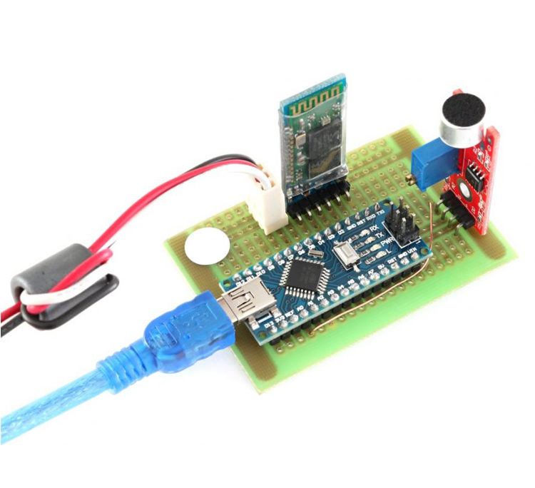
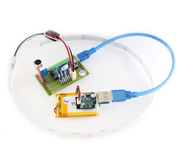
I created the prototype of the lampion on the universal printed circuit board to ensure good resistance to shocks. When the module is properly deployed, the connection is very simple and the soldering is minimal.
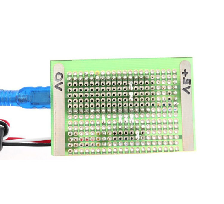
The jumpers are visible on the underside of the universal printed circuit board. These can easily be done by setting the temperature of the soldering tip to a minimum.
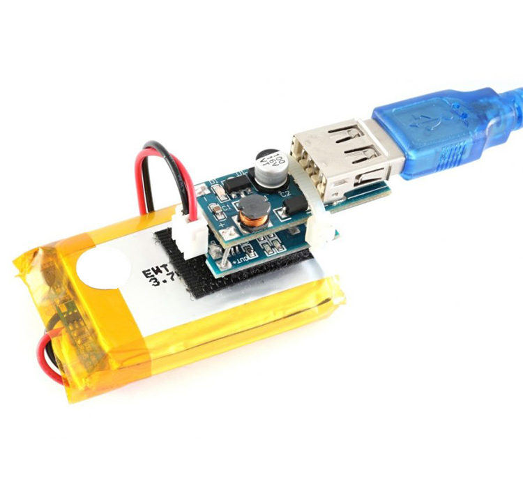
For example, we can power the entire lamp from USB PowerBank, but why not build your own solution with a high-quality LiPol battery? The whole construction is simple. The LiPol battery is connected to the charging module. It further supplies an upgrading drive that generates a 5 V supply voltage for the Arduino board.
Components used for Arduino lampion
1.Arduino Plate Arduino NANO
2.Bluetooth module HC-05 for communicating with your mobile phone
3.RGB NeoPixel LED Strap – Length 0.5 m
4.A high-sensitivity sound sensor for creating color music
5.Contact field with connecting wires for prototype creation
6.Universal printed circuit board for the final solution of the lamp
7.LiPol 3.7V 1800 mAh battery for lamp operation without external power supply
8.USB Charger LiPo protection for battery charging
9.Voltage Converter from 0.9 V to 5 V USB – Provides a 5 V supply for Arduin power
10.REGOLIT shade from IKEA
Well, imagine if you have a group of such colored balls in town at night. That would be a force.
So maybe you’ll meet her once.

